5.4 Detection Job in uniVision
Open the device website of the Machine Vision Device, select the tab Jobs, and open the current job in the uniVision 3 software.
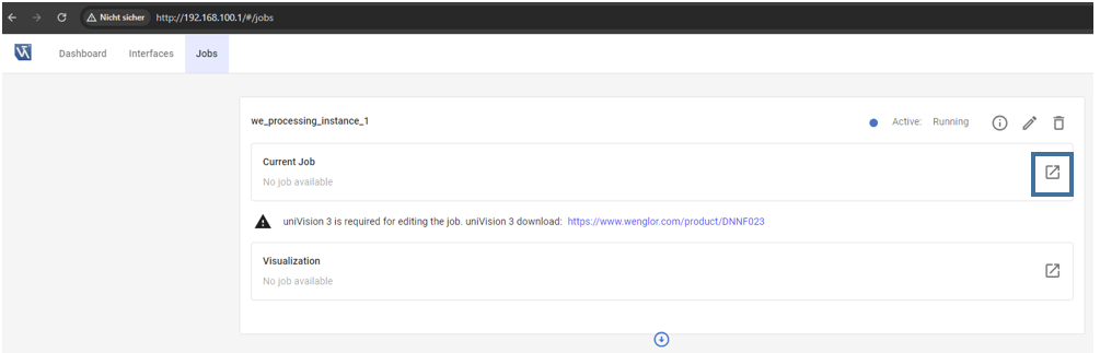
Load the template Pick objects with robot for easy setup.
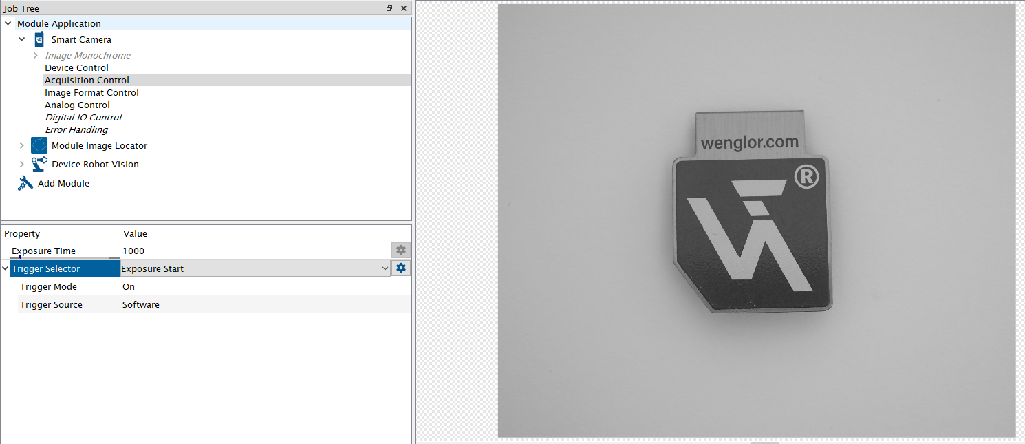
Adjust the focus and brightness of the camera to get a sharp and well-illuminated image. By default, Trigger Mode is set to On and Trigger Source to Software. Adjust Trigger Mode to Off and switch to Run Mode in order to adjust the camera image. Afterward, change Trigger Source back to Software. If working with color images, make sure that Create BGRA Image is active at the input camera (only relevant if working with URCap).
Teach your object at Module Image Locator (or Module Image Pattern Match). For details, check the operating instructions of the software wenglor uniVision 3 (DNNF023).
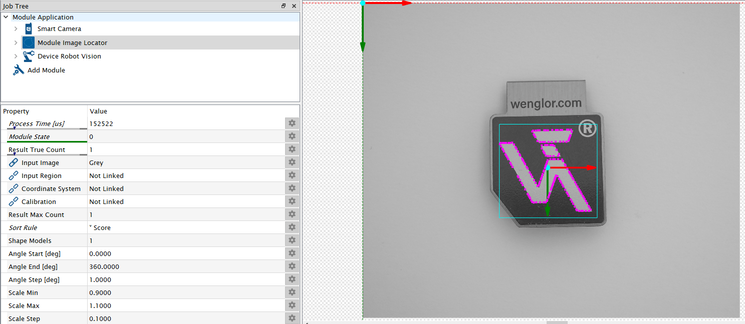
In the template, Device Robot Vision is already pre-configured to send the results to the robot server.
| Field | Explanation |
|---|---|
| Process Time [µs] | Process time to run the module in µs |
| Module State | Shows state of module:
|
| Output | Shows preview of the output sent to the wenglor robot server. |
| Shape Model Count | Defines the number of shape models (object types) used in the sub-module Shape Model Height Difference |
| Result Max Count | Defines the number of results used in the sub-module Result List. |
| Result True Count | Link the value with Result True Count of Module Image Locator or Module Image Pattern Match so that the robot knows how many objects are within the current image. By default, the value is 0. Linking Result True Count is mandatory so that the robot server knows how many objects are found in the current image. |
Sub-Module Shape Model Height Difference (number of entries depends on parameter Shape Model Count):
Height Difference to Calibration [mm] #...x: Defines the height difference of each shape model to the calibration plate. By default, the value is 0.
Note
- It is possible to pick different object types with different heights.
- Enter the object height relative to the surface of the calibration plate in mm. If the object is lower than the calibration plate plane, enter a negative number. If the object is higher, enter a positive number. Also use the height difference if height variations occur after the calibration process.
Sub-Module Result List (number of entries depends on parameter Result Max Count)
Link the result list of Module Image Locator or Module Image Pattern Match to the Result List of Device Robot Vision.
| Shape Model | Link the Shape Model (object type) for each result. By default, the value is 0. |
| X [px] | Link the x position for each result. Linking the x coordinate is mandatory. |
| Y [px] | Link the y position for each result. Linking the y coordinate is mandatory. |
| Phi (Z-Rotation) | [deg] Link the Phi value (z rotation) for each result. Linking Phi is mandatory. |
| Additional Value | Optionally link an additional string result (e.g. score value) for each result. |
Note
- It is possible to detect and pick multiple objects in a single image capture (if set up accordingly in the uniVision job).
- Offsets in x and y can be set directly in
Module Image LocatororModule Image Pattern Match. - Pixel results for x and y can only be used by the robot if they are distorted pixel coordinates. Modules without a calibration linked at the module calibration produce distorted pixel coordinates. If a calibration is linked at the module calibration, the module calculates undistorted pixel coordinates instead, which
Device Robot Visiondoes not support. Make sure that only distorted pixel coordinates are linked atDevice Robot Vision.
Save the detection job in the device projects folder on the Machine Vision Device. This job will later be used during the object detection in the robot program. Therefore, it is important to reuse the job name in the robot program.